BCE PCB Mounted Epoxy Vacuum Feedthroughs

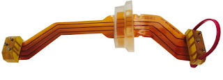
BCE is a leading manufacturer of printed circuit board mounted vacuum feedthroughs.

New epoxy compounds have been developed that rival glass and ceramic in performance. BCE is at the forefront of this development and leverages modern epoxy's unique properties to solve your feedthrough challenges.

FEATURES:
  • Custom shapes, angles and conductors no problem.
  • Run wires (and shielding), pneumatic tubing, or fiber-optic cables.
  • Cost effective compared to glass and ceramic.
  • Short runs and prototypes available quickly.
  • Meets NASA specs on outgassing.
  • Clear epoxy allows for visual inspection.
  • Mounting directly to printed circuit boards and flex-circuits.
  • Eliminates voltage drop or contact resistance.
Visit http://www.belilove.com/feedthroughs for more information.

BCE Flanged Gas Heater (Custom Electric Heating Element)

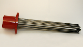
Here is an example of BCE's custom heating element design and manufacturing capabilities. This is their flanged gas heater.

Some of the design features are:

  • Heat gasses to 400°C - 450°
  • Body welded to pass 10⁻⁸ vacuum
  • All 304 SST materials (other available).
  • RoHS compliant parts and components.
  • Embedded thermocouple probe.
  • Can be used in gas chromatography and other applications.
  • Wire length/type are customer specified.


For more information visit http://www.belilove.com or call (510) 274-1990.

Doser Purging System Heating Element

Doser Purging System Heating Element
Doser Purging System
Heating Element
Gaseous nitrogen is used in the food and beverage industry to remove oxygen from products, thus increasing shelf life. The handling of liquid nitrogen through the piping and the injection systems that deliver the "nitrogen dose" into food and beverage containers presents unique challenges.

For food & beverage producers, lost production is calculated in downtime. Moisture and freeze-ups are the main contributor to downtime with production line gas dosing systems.  It takes only a very small amount of moisture to freeze up and stop equipment. It’s imperative maintaining reliable and productive dosing process and overcome moisture and frost contamination. The start-up and shut-down times for the dosing systems are another critical area for production efficiency when you consider many dosing systems requiring thaw periods of up to 24 hours.

BCE is pioneering the design of an electric heating element used in purging systems for nitrogen dosers. Heated purging systems remove moisture that migrates into the dosing system and cause freeze-ups, leading to poor operation or complete shut downs of the dosing system.

The purge heater is designed to heat a dry nitrogen gas supply to approximately 125 degrees F., which in turn, is piped to the doser system as an accelerant to thaw and dry the unit very rapidly. Depending on the dosing system, the net effect of using a purge heater is dramatic, with thawing and drying times reduced by 75%.

Key Benefits of Using an Electric Purge Heater
  • Better, more efficient control over moisture. 
  • 75% reduction in purge time. 
  • 66% reduction in start-up time. 
  • Cost savings from using less gas due to shorter purge times.
z

New Compact Heater for Clean Liquids and Gases

The BCE Mini Clean Flow Heater operates in a liquid or gas stream providing very fast response times and accurate control capability.

The heating elements in the Mini Clean Flow Heater are isolated electrically from the process media, protecting them from contaminants and providing long life.
  • Designed for heating of clean gases or liquids 
  • Gas flow passes over an enclosed heated body; not exposed to resistive elements (ni-chrome) 
  • All parts exposed to gas flow are constructed of 304 stainless (other material available) 
  • High temperatures 
  • Custom wattages, voltages, inlet and outlet fittings are available. 
  • Made in U.S.A.

Maintaining Close Temperature Control of a Fluid Process Flow

Temperature control is a common operation in the industrial arena. Its application can range across solids, liquids, and gases. The dynamics of a particular operation will influence the selection of instruments and equipment to meet the project requirements. In addition to general performance requirements, safety should always be a consideration in the design of a temperature control system involving enough energy to damage the system or create a hazardous condition.

Let's narrow the application range to non-flammable flowing fluids that require elevated temperatures. In the interest of clarity, this illustration is presented without any complicating factors that may be encountered in actual practice. Much of what is presented here, however, will apply universally to other scenarios.
What are the considerations for specifying the right equipment?


Know your flow. 

First and foremost, you must have complete understanding of certain characteristics of the fluid.
  • Specific Heat - The amount of heat input required to increase the temperature of a mass unit of the media by one degree.
  • Minimum Inlet Temperature - The lowest media temperature entering the process and requiring heating to a setpoint. Use the worst (coldest) case anticipated.
  • Mass Flow Rate - An element in the calculation for total heat requirement. If the flow rate will vary, use the maximum anticipated flow.
  • Maximum Required Outlet Temperature - Used with minimum inlet temperature in the calculation of the maximum heat input required.


Select system components with performance to match the project.

  • Heat Source - If temperature control with little deviation from a setpoint is your goal, electric heat will likely be your heating source of choice. It responds quickly to changes in a control signal and the output can be adjusted in very small increments to achieve a close balance between process heat requirement and actual heat input. 
  • Sensor - Sensor selection is critical to attaining close temperature control. There are many factors to consider, well beyond the scope of this article, but the ability of the sensor to rapidly detect small changes in media temperature is a key element of a successful project. Attention should be given to the sensor containment, or sheath, the mass of the materials surrounding the sensor that are part of the assembly, along with the accuracy of the sensor.

    The location of the temperature sensor will be a key factor in control system performance. The sensing element should be placed where it will be exposed to the genuine process condition, avoiding effects of recently heated fluid that may have not completely mixed with the balance of the media. Locate too close to the heater and there may be anomalies caused by the heater. A sensor installed too distant from the heater may respond too slowly. Remember that the heating assembly, in whatever form it may take, is a source of disturbance to the process. It is important to detect the impact of the disturbance as early and accurately as possible.
  • Controller - The controller should provide an output that is compatible with the heater power controller and have the capability to provide a continuously varying signal or one that can be very rapidly cycled. There are many other features that can be incorporated into the controller for alarms, display, and other useful functions. These have little bearing on the actual control of the process, but can provide useful information to the opeartor. 
  • Power Controller - A great advantage of electric heaters is their compatibility with very rapid cycling or other adjustments to their input power. A power controller that varies the total power to the heater in very small increments will allow for fine tuning the heat input to the process.
  • Performance Monitoring - Depending upon the critical nature of the heating activity to overall process performance, it may be useful to monitor not only the media temperature, but aspects of heater or controller performance that indicate the devices are working. Knowing something is not working sooner, rather than later, is generally beneficial. Controllers usually have some sort of sensor failure notification built in. Heater operation can be monitored my measurement of the circuit current. 


Safety Considerations

Any industrial heater assembly is capable of producing surface temperatures hot enough to cause trouble. Monitoring process and heater performance and operation, providing backup safety controls, is necessary to reduce the probability of damage or catastrophe.
  • High Fluid Temperature - An independent sensor can monitor process fluid temperature, with instrumentation providing an alert and limit controllers taking action if unexpected limits are reached.
  • Heater Temperature - Monitoring the heater sheath temperature can provide warning of a number of failure conditions, such as low fluid flow, no fluid present, or power controller failure. A proper response activity should be automatically executed when unsafe or unanticipated conditions occur.
  • Media Present - There are a number of ways to directly or indirectly determine whether media is present. The media, whether gaseous or liquid, is necessary to maintain an operational connection between the heater assembly and the sensor. 
  • Flow Present - Whether gaseous or liquid media, flow is necessary to keep most industrial heaters from burning out. Understand the limitations and operating requirements of the heating assembly employed and make sure those conditions are maintained. 
  • Heater Immersion - Heaters intended for immersion in liquid may have watt density ratings that will produce excessive or damaging element temperatures if operated in air. Strategic location of a temperature sensor may be sufficient to detect whether a portion of the heater assembly is operating in air. An automatic protective response should be provided in the control scheme for this condition.
Each of the items mentioned above is due careful consideration for an industrial fluid heating application. Your particular process will present its own set of specific challenges with respect to performance and safety. Share your requirements with process heat experts, combining your process knowledge with their expertise to develop safe and effective solutions.

Heaters for Process Air and Gases

electric heaters for process air or gas streams
Examples of process air heaters
Courtesy Hotwatt
Many process applications require heating of an air or gas stream. There is a wide variety of electric heating units specifically designed for processing flowing streams of air or non-flammable gas.

The primay selection criteria for a process air heating unit should be the heating capacity or wattage. Determine the maximum flow rate, inlet and outlet temperatures, then apply a simple formula from the document included below to find the minimum watt rating for a heating unit. Outlet temperatures can range to 1000°F (540°C) and flow rates to 200 scfm. Custom units can accommodate applications beyond those limits.

The outlet temperature can be controlled in a number of ways. One is to regulate the power applied to the heater. This would be applicable to a process that required a constant or minimum air flow rate. If the flow rate can be varied, another method of temperature control is available. Maintaining constant power to the heater and varying the air flow rate can serve as a means of controlling the output temperature.

Various connection sizes and fittings can be included in the heater assembly design to accommodate its incorporation into a process equipment train. Share your process heating requirements and challenges with experienced application engineers, combining your own process knowledge with their product application expertise to develop effective solutions.


Industrial Process Temperature Sensor Comparison

industrial thermocouples
Array of thermoucouple assemblies
Courtesy Durex
It's always useful to have quick references for things. Durex, a globally recognized manufacturer of electric heating solutions, published the Temperature Sensor Element Selection Guide included below in a recent blog posting. It provides a consolidated comparison of the four primary temperature sensing devices used for industrial process control. Many will find it useful, so we share it with you here.

All the technical expertise needed for your process heating challenges is readily accessible at BCE. Share your heating challenges with experts, combining your process and application knowledge with their expertise to develop effective solutions.


Flanged and Screw Plug Electric Heating Assemblies for Industrial Applications

flanged tubular electric heater assembly
Flanged Tubular Electric Heater Assembly
Hotwatt
Electric heating, though not the most energy efficient means of delivering heat, provides some distinct advantages as a means of controlling the temperature or thermal component of fluids and solids throughout commercial and industrial settings.

Tubular elements are a common form of electric heater. Essentially a metal tube with resistance wire and electrical insulation inside, tubular elements can be configured into almost uncountable shapes and sizes. Manufacturers typically offer a range of standard sizes and ratings, but that should never deter you from making contact to discuss your ideas for a custom arrangement.

Two mounting schemes that are readily used on tanks or other vessels are the screw plug and flanged heater assemblies. In each case, tubular heaters are bent in a "U" shape and fitted into either a pipe flange or a threaded plug. A junction box encloses the electrical terminations for the heating elements, providing a single ended assembly that can be easily mounted to an industrial standard mechanical connection. These assemblies are useful for tank or vessel OEMs that wish to provide a fluid heating option to their customers.
tubular electric heaters screw plug mounting
Examples of Screw Plug Electric Heaters
Hotwatt

Electric heat enables a properly configured controller to proportion heat into a subject fluid across a wide range, from very small packets that could be fractional percentages of full capacity to the fully available output of the heater. The units are compact, rugged, and can be configured to accommodate a broad array of industrial environments and applications.

Selecting or specifying a unit is uncomplicated. Determine the amount of heating capacity needed, then select the assembly mounting type (flange, screw plug, or other). Select an element sheath material that is compatible with the process media and a termination enclosure that suits the surrounding environment. Application assistance is available from product specialists who are well versed in the available options and can help you specify an assembly that provides excellent performance and an extended service life.

BCE Epoxy Vacuum Feedthroughs: When You Need to Pass a Signal Through A Vacuum Chamber Wall


Equipment manufacturers and scientific researchers are continually challenged with supplying power, fiber-optic, control, and monitoring cables into (and out of) sealed vacuum vessels. Whether due to space restrictions, special geometries, or number and type of conductors, standard glass-to-metal or ceramic feedthroughs never quite fit the bill. Unfortunately, because of limited options, many designers are forced to compromise and go for an off-the-shelf solution.

You don't have to compromise anymore.  EPOXY TO THE RESCUE. 

During the past decade, new epoxy compounds have been developed that rival glass and ceramic in performance. BCE is at the forefront of this development and leverages modern epoxy's unique properties to solve your feedthrough challenges.

With modern epoxy feedthroughs, any kind of standard or custom connector is sealed in a completely potted, high-performance, clear epoxy compound. Epoxy seals offer countless design options, and most amazingly, performance equal to or better than glass or ceramic. Better yet, pricing is very competitive and quick turn-around for prototypes and short production runs are not a problem.

BCE custom epoxy vacuum feedthroughs offer the best choice in application flexibility, cost, and high performance. Epoxy feedthroughs are the right product for today’s fast moving markets. If you have to pass an electrical, pneumatic, or fiber-optic signal through a vacuum chamber wall, THINK OF BCE!

New BCE Expoxy Vacuum Feedthrough Video

Check it out ....

What is an Atmospheric-pressure Chemical Ionization (APCI) Heater?

APCI heater
Diagram of APCI highlighting heating element.
For more information
on APCI heaters call BCE
at (510) 274-1990 or visit
Belilove.com/apci-heater

Mass spectrometers work by removing target components as ions in a gas phase, and then detect them as ions under high vacuum. In the development of liquid chromatography – mass spectrometry (LC-MS) a significant problem arises from the vaporization from liquid mobile phase when large amounts of gas can be introduced into the mass spectrometer (MS), and thus decreasing the level of vacuum and impinging the ability of ions to reach the detector.

Dealing with the mobile phase and preventing the introduction of the smallest amounts of gas is critical in LC-MS.

Atmospheric-pressure Chemical Ionization (APCI)

One solution is to use Atmospheric-pressure Chemical Ionizationa specific type of chemical ionization. Atmospheric-pressure Chemical Ionization vaporizes solvent and sample molecules by spraying the sample solution into a heater (approx. 400 °C) using a carrier gas, such as Nitrogen. The solvent molecules become ionized via corona discharge and generate stable reaction ions in the mass spectrometer.

An APCI heater is a specialty electric heating element that has a resistance temperature detector (RTD) built-in for accurate temperature control, a .016” ID capillary tube in the center of the heater axis and a maximum operating temperature is up to 400°C.  This assembly also comes complete with the connector plug.

For more information on APCI heaters contact BCE at (510) 274-1990 or visit http://www.belilove.com/apci-heater.


Hotwatt Electric Heating Elements for OEM, Laboratory, and Industrial Applications

Hotwatt
Hotwatt Electric Heating Elements
Hotwatt is a leader in manufacturing resistance heating elements. They have an extensive product line that includes cartridge heaters, immersion heaters ideally suited for heating various liquids, air process heaters for providing hot air and gas up to fourteen hundred degrees, stainless steel strip and finned strip heaters in various sizes, self-contained one piece assembly oil in rope heaters; tubular and finned tubular heaters which have been specially built to resist impact, vibration, corrosion, and temperature extremes; extremely versatile band heaters for a multitude of applications; and ceramic and crankcase heaters for custom solutions. Hotwatt's technical information and accessory items ensure that hard what has everything you need for complete thermal system.

Contact BCE for more information at (510) 274-1990 or visit http://www.belilove.com.

Capillary Source Heater Assembly

APCI heater
APCI heater from BCE (Belilove Company-Engineers)
Atmospheric pressure chemical ionization (APCI) a widely used ionization technique in mass spectrometry, is the ability to easily ionize and detect non-polar or slightly polar species.

The APCI heater has a Resistance Temperature Detector (RTD) built into it. The heater assembly has a .016” ID capillary tube in the center of the heater axis. The maximum operating temperature is up to 400°C. This assembly comes complete with the connector plug.

The APCI sample is typically dissolved in a solvent and pumped through a heated capillary. Nitrogen gas is introduced the gaseous solvent is heated up to 400°C the sample is then ionized by corona discharge.

For more information on capillary source heaters, or any custom electric heating element, contact:

BCE
www.belilove.com
21060 Corsair Blvd
Hayward, CA 94545
(510) 274-1990) 274-1990

Belilove Company-Engineers Gains ITAR Registration. So What's ITAR?

ITAR
BCE (Belilove Company-Engineers) is ITAR registered.
The International Traffic in Arms Regulations, known as ITAR, are export control regulations run by the US Department of State. BCE is now ITAR registered. So what does this mean?

Understanding and complying with The International Traffic in Arms Regulations (ITAR) is necessary for companies in the supply chain to operate efficiently and expand business opportunities world-wide.

The U.S. Government requires all companies who manufacture, export, or broker defense related articles, defense related services, or technical data to be ITAR compliant. In as much, compliance with the continuously evolving export regulations is essential for any company that does business with manufacturers or contractors who compete in the global marketplace.

ITAR is designed to help ensure that defense related technology does not end up in enemy hands. ITAR relates directly to defense-related applications.  Items specifically designed or otherwise intended for military end-use are listed on the United States Munitions List (USML) and are therefore controlled by International Traffic in Arms Regulations (ITAR). The program is administered by the Directorate of Defense Trade Controls (DDTC) at the State Department.

Products, services, and information all fall under ITAR regulations, with the most notable items being “Significant Military Equipment (SME)”. These are the most controlled. Examples are tanks, ships, helicopters, and explosives. However, there are many other "not so obvious" items listed on the USML,  or used in the supply chain, and providers of these articles must follow ITAR as well.

To be ITAR COMPLIANT, a company needs to register with the Directorate of Defense Trade Controls and fully understand what is required for compliance. The company must understand and abide by the ITAR as it applies to any of their United States Munitions List related goods or services, and the company certifies that they comply with ITAR when they providing materials or services to a USML prime exporter.

For more information, visit The International Traffic in Arms Regulations website.

Electric Heaters 101: Get the Heat Out of the Heater

cartridge heater
Internal view of swaged cartridge heater.
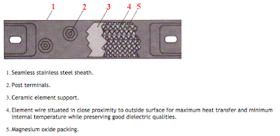
Metal-clad electric heating elements share one very common and very important requirement for optimal performance - get the heat away from the resistance wire and into the work as efficiently as possible.

At the heart of most resistance type electric heaters is a nichrome alloy wire, or ribbon, referred to as the heating "element". It acts as a resistor to the electrical current and gives off heat. With sheathed heaters, the heating element is then wrapped in some sort of electric insulating material such as mica or magnesium oxide (MgO), and then encased in a metallic sheath. Unfortunately, both the electric insulator and the metallic sheath act as heat insulators to some degree, which cause the nichrome wire to get very hot. Nichrome wire has a melting point of 1400 deg. C (about 2500 degrees F). While this sounds high, the wires and ribbons can easily exceed these temperatures in normal operation when not allowed to adequately conduct heat.

Very often electric heater failure can be directly attributed to poor conductivity between the heating element and the process medium. Whether it be a cartridge, strip, band, duct or immersion heater the principle is the same - lower resistance wire temperatures equal longer heater life.

When applying cartridge heaters, special care has to be taken to the bore tolerance of the hole where the heater is inserted. The tighter the bore tolerance, the more efficiently the high internal wire temperatures are conducted away.  Tolerances of several thousandths of an inch can change the life expectancy of a cartridge heater significantly.

Strip and band heaters require tight, full surface area clamping to maximize life and performance, while duct heaters and immersion heaters require circulation to transfer heat away from the element, and keeping resistance wire temperature within reasonable operating limits.
strip heater
Internal view of band & strip heater.

Any situation where the heater is exposed to a stagnant air gap (or stagnant fluids) will most likely result in over temperature of the wire and failure at that point.  With this in mind, anyone applying traditional resistance type, electric heating elements must be very aware of maintaining very intimate contact between the heating element and the item or process being heated.

Whenever applying electric heating elements, the consultation of an applications expert is always recommended. They will be able to consider many other operational factors such as wire watt density, conduction properties, control scheme and overall thermal system dynamics.

Process Heaters, Furnaces and Fired Heaters: Improving Efficiency and Reducing NOx

process heater
Process Heater
(courtesy of
AMETEK Process
Instruments)
A process heater is a direct-fired heat exchanger that uses the hot gases of combustion to raise the temperature of a feed owing through coils of tubes aligned throughout the heater. Depending on the use, these are also called furnaces or red heaters. Some heaters simply deliver the feed at a predetermined temperature to the next stage of the reaction process; others perform reactions on the feed while it travels through the tubes.

Process heaters are used throughout the hydrocarbon and chemical processing industries in places such as refineries, gas plants, petrochemicals, chemicals and synthetics, olefins, ammonia and fertilizer plants. Some plants may have only two or three heaters while larger plants can have more than fifty.

Most of the unit operations in these plants require red heaters and furnaces. These operations include:
  • Distillation 
  • Fluidized Catalytic Cracking (FCC) 
  • Alkylation 
  • Catalytic Reforming 
  • Continuous Catalyst Regeneration (CCR) 
  • Thermal Cracking 
  • Coking 
  • Hydrocracking 
Typical process heaters can be summarized as follows: 
  • Start-Up Heater — Starts-up a process unit where it is required to heat up a fluidized bed of catalyst before adding the charge. 
  • Fired Reboiler — Provides heat input to a distillation column by heating the column bottoms and vaporizing a portion of it. Used where heat requirement is greater than can be obtained from steam. 
  • Cracking Furnace — Converts larger molecules into smaller molecules, usually with a catalyst (pyrolysis furnace). 
  • Process Heater — Brings feed to the required temperature for the next reaction stage. 
  • Process Heater Vaporizer — Used to heat and partially vaporize a charge prior to distillation. 
  • Crude Oil Heater — Heats crude oil prior to distillation. 
  • Reformer Furnace — Chemical conversion by adding steam and feed with catalyst.
Read the full document below:

On-Off Temperature Control Using PLC Ladder Logic

on off control
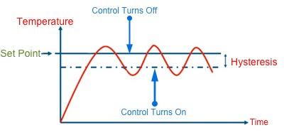
Diagram of on / off control.
In control theory, an on–off controller is a feedback controller that switches abruptly between two states. It is often used as a control method for a process which can tolerate an ongoing, changing band of change, referred to as the hysteresis. A very common example for temperature are residential thermostats. They control the temperature of your home, turning off at your comfort setting, then after some significant change occurs, and they turn on again to eliminate that difference. The process cycles continually.

A common method of temperature control is an on/off control system using comparison instructions in a PLC program where outputs are energized until the set point is reached.

The video below provides a temperature control example where the heater turns on when the temperature falls to or below 597 degrees, and turns off when the temperature reaches 603 degrees or more.

To control the circuit, S1 is programmed in the heater output circuit. Addressed to the move instruction is a thermocouple that provides an analog value to the temperature. The temperature is moved from the source to the destination when S1 is activated and is displayed on the LED panel.

Using the less than or equal to, and greater than or equal to, instructions addressed to the same integer file the source values have A and B are compared to control the heater. With source a less than source be at the less than equal to instruction, the low temp and heater outputs are enabled. The heater remains on as long as the low temp output is true and the high temp output is false.

As the temperature rises above source B at the less than or equal to instruction, low temp turns off and heating continues. Reaching 603 degrees or more, the high temp output is enabled, since source A is equal to source B of the greater than equal to instruction.

When the high temp output is true, the heater turns off and remains of until the temperature reaches 597 or lower.  The cycle is repeated to maintain the average set point temperature at the other at 600 Fahrenheit.


Experience is Key When Applying Custom Electric Heating Elements

Electric Heater Design Expert
Heater design expertise is
readily available from your
Technical Sales Rep
Designing and applying custom electric heating elements are best completed and accomplished through the proper application of the right resources. One of the most available and important sources of high level technical knowledge is a vendor's local Technical Sales Rep. Their assistance is readily available and their consultative value is very high.  Bringing in a Technical Sales Rep will have a big bearing on a successful task or project completion.

Many Technical Sales Reps are degreed engineers. If they don't have an engineering degree, you'll find they have years of empirical application knowledge from working on many, many projects. You'll also find that many have worked at manufacturer's factories and know the in's and out's of production as well as anyone.

Consider these elements the Technical Sales Rep brings to your thermal system design project:

Custom heating element
Watt densities? Thermal profiles?
Distributed wattage?
There's a lot to know.
Product and Application Knowledge: Your Technical Sales Rep has probably seen hundreds, if not thousands, of custom heating requirements. They deliver a mental encyclopedia of product offerings, application insights, and broad spectrum of capabilities. They also have information regarding what products are in development that can give you the competitive edge. Much of this information resides in the Reps head, and is not generally accessible to the public via the Internet.

Experience: As a project engineer, the selection and incorporation of a new heater design may be all new to you. You may be treading on fresh ground with little or no experience in the nuance of electric heaters. There can be real benefit in connecting to a knowledgeable source, with years of past design and application experience, that will save you time, money, and effort.

Access: Technical Sales Reps work closely with a variety of manufacturers, and may even have in-house prototyping or manufacturing capabilities at their own companies. This gives you, the design engineer, a connection to “behind the scenes” manufacturer contacts with essential information not publicly available. The technical sales rep knows people, and makes it his/her business to know the people that can provide answers to your electric heating and custom thermal system application questions.

So, in this age of doing your own research and self-educating on the Internet, let's not forget the importance of a face-to-face visit with someone who can really help - your Technical Sales Rep. You'll be very pleased with the information they can provide to make your job easier and the quality of your product better.

Have a custom heater job? Contact BCE now!
www.belilove.com(510) 274-1990

Heat Transfer 101 for Industrial and OEM Applications

heat transfer
Heat transfer
shown by
melting ice.
When you need to apply heat in industrial applications, or for OEM part heating, everyone works under the same Laws of Thermodynamics. Whether your using electric heating elements or heating by steam, its imperative to understand the basics of heat and heat transfer.

Heat transfer is the movement of heat from one body or substance to another by radiation, conduction, convection or a combination of these processes. When heating a pan of water over a gas flame for example, all three forms of heat transfer are taking place. Heat from the flame radiates in all directions. Conduction takes place with the transfer of heat from the burner to the metal pan. This heat transfer is also responsible for making the handle hot after a period of time. The water is heated by the process up convection which is a circular movement caused by heated water rising and cold water falling.

The process of heat transfer also occurs when an object cools. If a mug of hot coffee is left standing on a cold kitchen countertop its temperature will gradually decrease as heat is lost. The heat energy dissipates by conduction through the mug to the table top, by convection as the liquid rises cools, and sinks, and by the radiation of heat into the surrounding air.

One way to conserve the heat of a liquid and prevent heat transfer is to place it in a thermos. The use use of a vacuum chamber with silvered surfaces along with low conductive materials can greatly improve the amount of heat or cold that is lost to the surrounding environment.

In between the silver glass walls of a thermos lies a vacuum. In the case of a hot liquid, heat transfer by convection through the vacuum is greatly restricted due to the absence have air molecules necessary to facilitate the transfer of heat. The lack of physical contact between the inside and outside walls of the thermos due to this airless space also greatly inhibits the movement of heat by conduction.

Heat loss by radiation is prevented by the silvered walls reflecting radiant energy back into the thermos. Some conduction of heat through the stopper and glass can be expected, but this too is limited because they are made of materials with very low conductivity. Thus the temperatures of both hot and cold liquids can be maintained by a properly designed thermos that limits the transfer energy through radiation, convection, and conduction.

Heat capacity is the amount of heat required to change the temperature of an object or substance by one degree Celsius. The heat capacity of water varies depending on its phase. As solid ice, the heat capacity of water is .5 calories per gram for every one degree Celsius, which means it takes half a calorie to raise the temperature of one gram of ice one degree Celsius. As a liquid, waters heat capacity is one calorie per gram for every one degree Celsius. So it takes one calorie of heat energy to raise one gram of water one degree Celsius.

The processes a phase change between solid liquid and gas also require a specific amount of heat energy. The amount of energy required to change a liquid into a solid or a solid into a liquid is known as heat of fusion. The amount of heat required to change one gram of ice to water is 80 calories. Similarly, the heat of vaporization is the energy required to transform a liquid into a gas. It requires 540 calories to change one gram of liquid water into a gas. With these values its easy to calculate exactly how many calories of heat energy are required to transform one gram of ice, at absolute zero, to steam.

To warm 1 gram a ice from -273 degrees Celsius, to 0 degrees celsius, would be 273 times .5 gram per calorie, or about 140 calories. The phase change of one gram a ice to liquid water requires 80 calories. Then to heat the water from zero degrees Celsius to 100 degrees Celsius with the heat capacity at one calorie per gram, would require 100 calories. The final phase change of one gram of boiling water to steam would require an additional 540 calories. Adding all of these values together yields 860 calories, the amount of heat energy it takes to transform one gram of ice, at absolute zero, to steam.

Epoxy Vacuum Feedthroughs for Medical Equipment, Analyzers, and R&D Laboratories

epoxy feedthrough
The challenges of getting data and
control sensors inside
vacuum equipment.
Scientists and researchers are continually challenged to come up with better ways to read data inside a vacuum environment. Traditional ceramic and glass-to-metal vacuum feedthroughs don’t offer the flexibility of design required. Unique varieties of control and data signals have to pass through the wall. Not only are electrical power and control signals being passed, but fiber optic cables and pneumatic tubing may be included. Ever changing variables, such as the number and types of connectors, unique geometries, and limited available space, make it very difficult to find an off-the-shelf feedthrough. As a result, designers have traditionally been forced to make compromises and specify a feedthrough with some, but not all, of the desired specifications.

custom epoxy feedthrough
Custom epoxy feedthrough by BCE
This reality has led to significant gains in custom epoxy feedthrough development. Epoxy feedthroughs overcome design restrictions. New epoxy properties have been developed that rival ceramic and glass in performance. High performance, clear epoxy potting opens the door for researchers to specify the exact number and type of wires, fiber optic cables, or any other insert they require.

Manufacturers of epoxy feedthroughs can provide a virtually limitless variety of wires, cables, or tubes along with the added benefit of fast prototyping and small production runs - perfect for the research and manufacturing community.

Epoxy vacuum feedthroughs are quickly becoming the preferred vacuum entry device because:
  • Can accommodate custom conductors, angles, and shapes.
  • Prototypes with the exact number and type of have fiber-optic cables, pneumatic tubing, or run wires.
  • Electrical shielding is not a problem.
  • Epoxy feedthroughs are cost-effective.
  • Comply with outgassing specifications.
  • Allow for visual inspection when clear epoxy used.
  • Feedthroughs can be mounted directly to flexible circuits and printed circuit boards.
  • Elimination of contact resistance.
With the development of epoxy feedthroughs medical device companies, analyzer manufacturers, laboratories, aerospace companies, and other R&D facilities can design their equipment based on optimal size, cost and performance, and not be forced to compromise by ceramic and glass-to-metal feedthroughs limitations.

Because of the constant pressure on vacuum equipment researchers and OEM designers for “better, faster, smaller”, it’s clear that epoxy feedthroughs provide flexibility and options which allow for more efficient and creative design.

For more information regarding epoxy vacuum feedthroughs, contact:
BCE
www.belilove.com
(510) 274-1990

Epoxy Vacuum Feedthroughs for Electrical and Fiber Optic Applications

epoxy vacuum feedthroughs
Epoxy vacuum feedthroughs
provide faster prototyping and
meet customer needs.
More and more OEMs and research facilities are turning to epoxy feedthroughs for their vacuum chamber challenges. New epoxies are available that rival glass and ceramic feedthroughs in performance. Faster prototyping, and lower short-run costs are making epoxy feedthroughs very attractive.

Ceramic and glass-to-metal feedthroughs typically are not available in the exact form required by scientific researchers and equipment manufacturers. There is a tendency to settle or accept off-the-shelf feedthroughs as a compromise, thinking that custom ceramic or glass feedthroughs in small quantities would break the bank, not to mention take forever to deliver. Not true.

epoxy feedthrough
Epoxy feedthrough
Today’s epoxy vacuum feedthroughs make prototyping and manufacturing easier, with higher production output and lower overall costs. Here are some of the features that make this true:
  • Custom conductors, angles, and shapes are not a problem
  • Prototype designs can be provided with fiber-optic cables, pneumatic tubing, and wires (with or without shielding)
  • Compared to ceramic or glass, custom epoxy feedthroughs are cost-effective
  • Feedthroughs comply with NASA outgassing specs
  • Visual inspection is possible because of the clear epoxy used
  • The feedthroughs can be mounted directly to flex-circuits and printed circuit boards
  • Tighter specification can be achieved because contact resistance and voltage drop is eliminated

Epoxy vacuum feedthroughs come custom built to your unique specifications and ensure your equipment performs to the level you specify, so it's important to work with an experienced, capable manufacturer of epoxy feedthroughs. In today’s ultra-competitive marketplace, working with the right partner can mean the difference between success and failure. Manufacturer’s are constantly looking smaller, more compact parts, with faster deliveries and lower costs. Pick a vendor for your vacuum feedthroughs that understands this and has the in-house technology and processes to keep you ahead of the curve.

For more information on epoxy vacuum feedthroughs, contact:
BCE
(510) 274-1990

Ceramic Thick-Film Heaters for OEM Analytical and Medical Equipment

ceramic heating element
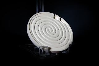
Ceramic heating element
Manufacturers of laboratory and process analytical equipment, as well as medical equipment, are continually challenged to make products smaller and more compact. Smaller, more efficient components are always in demand. Providing heat for sample stability or a chemical reaction is a common requirement. There's an ongoing challenge to find smaller and more efficient electric heaters.

Many traditional electrical heating elements are limited in size and efficiency due to the balance required between conductor temperatures and the the heat transfer properties of the dielectric material used in their construction. Sometimes the mass required to insulate electrically is at odds with the ability to drive the heat into the part.  Metal sheathed heaters use compacted magnesium oxide, or wafers of mica for dielectric. While these provide good electrical insulation, they also inhibit thermal transfer from resistance element to the external part. Flexible heating elements use a variety of rubbers or fluoropolymer elastomers that sandwich the resistance element. While these designs are dielectrically strong, and allow for excellent heat transfer, they are limited by the maximum operating temperatures and watt densities of the elastomer.

A newer, alternative technology is “thick-film” ceramic heaters, a process of depositing a resistor “trace” of tungsten paste on top of a ceramic part in a process very similar to screen printing. The deposition process allows for close control of thickness and width of the resistor, thus accurately controlling the conductor resistance, wattage, watt density, and uniformity of the heated part.

The use of ceramics as the heater body (referred to as a heated part), has many advantages. Ceramics are chemical inert, offer excellent thermal conductivity, impervious to moisture, and are very durable. The downside to using ceramics as heaters, however, is the difficulty in machining to very tight tolerances. In recent years though, many of the ceramic machining hurdles have been overcome through advanced ceramic machining processes.

In the early years of development thick-film ceramic heaters had a few major challenges. Dealing with mis-matched expansion coefficients between the ceramic substrate and the conductor trace was considerable. Years of research now have yielded excellent data on compatible materials making this problem much less significant. Another challenge is controlling the tolerance and repeatability of the heater resistance from part-to-part. Improvements and advancement in this area are made possible with laser etching, tighter screening procedures, and advanced machining.

The use of ceramics provided many interesting possibilities in heater design, and many materials were tested and researched. The most common ceramics used for thick-film heaters today are alumina (Al2O3), silicon nitride (Si3N4), beryllium oxide (BeO), and aluminum nitride (AlN). Each material has its own unique chemical and physical properties, but all exhibit good thermal conductivity and good dielectric properties.

The combination of excellent thermal conductivity, high dielectric, high watt densities, precise thermal profiling, and custom shapes and sizes that make thick-film ceramic heaters so attractive to equipment manufacturers. Providing more heat in smaller areas is easier than with traditional heaters. Additionally, some of the ceramics used are non-contaminating and moisture-proof, making them excellent candidates for clean and ultra-clean applications.

Ceramic thick-film heaters have many advantages over metal or elastomer sheathed heaters beyond just providing a more compact component. They are very fast acting, durable, moisture proof,  and contamination proof. They can be designed and machined to virtually any size or shape, watt density, voltage, and distributed wattage profile. While the initial design and prototyping requires investment in time and money, the resulting product can be mass produced economically and with repeatable accuracy and quality.

For more information, contact:
BCE
(510) 274-1990
www.belilove.com
Suggested Watt Densities for Electric Heating Elements

watt density in electric heaters
Always consider proper watt density
for your electric heater application.
Reprinted with permission from Hotwatt

The rates below are recommended watt densities for use with various materials. Safe values vary with operating temperature, flow velocity, and heat transfer rates. In general, the higher the material temperature, the lower the watt density should be, especially those materials which coke or carbonize, such as oils. Watt densities should be low if a material is being heated to a temperature near where the change of state to a vapor occurs (water to steam @ 212°F) since the vapor state has much poorer heat transfer capabilities.

Material being heated Maximum Operating Temp.°F Maximum Watts Per Sq. In.*
Acid Solutions:
   Acetic
   Chromic (5%)
   Citric
Ferric
   Chloride (40%)
Hydrochloric
Nitric (50%)
Sulphuric

212
Boiling
Boiling
Boiling

150
Boiling
Boiling

40
40
40
40

30
40
30
Alkali & selected oakite cleaning solution 212 40
Asphalt binder, tar, other viscous compounds 200
300
400
500
8
7
6
5
Caustic Soda 2%
                    10%
                    75%
210
210
180
45
25
25
Coffee (Direct Immersion) Boiling 90
Dowtherm A®
   flowing at
   1 ft/sec or more
   Non-flowing


750
750


22
10
Ethylene glycol 300 30
±Fuel Oils
   Grades 1 & 2 (Distillate)
   Grades 4 & 5 (Residual)
   Grade 6 & Bunker C
   (Residual)
200
200
160
22
13
8
Gasoline, kerosene 300 20
Glue (heating indirectly using water bath Lead-Stereotype pot) 600 35
on
casting
Liquid ammonia plating baths 50 25
** Lubrication Oils
   SAE 10, @ 130°F
   SAE 20, @ 130°F
   SAE 30, @ 130°F
   SAE 40, @ 210°F
   SAE 50, @ 210°F

250
250
250
250
250

22
22
22
13
13

* * Some oils contain additives that will boil or carbonize at low watt densities. Where oils of this type are encountered, a watt density test should be made to determine a satisfactory watt density.


Material being heated Maximum Operating Temp.°F Maximum Watts Per Sq. In.*
Metal melting pot 500 to 900 20-27
Mineral oil 200
400
20
16
Molasses 100 2-3
Molten salt bath 800-950 40
Molten tin 600 20
Oil draw bath 600
400
20
24
Paraffin or wax 150 16
Photographic solutions 150 70
Plating solutions:
   Cadmium plating
   Chrome plating
   Copper plating
   Nickel plating
   Tin plating
   Zinc plating

40
40
40
40
40
40
Salt Bath 900 30
Sea Water Boiling 90
Sodium cyanide 140 40
Steel tubing cast into aluminum 500 to 750 50
Steel tubing cast into iron 750 to 1000 55
Heat transfer oils
   flowing at 1 ft/sec or more
500
600
650
750
22
22
22
15
Trichloretylene 150 20
Vapor degreasing solutions 275 20
Vegetable oil (fry kettle) 400 30
Water (process) 212 60
Water (washroom) 140 80-90

* Maximum watt densities are based on heated length, and may vary depending upon concentration of some solutions. Watt density should be kept as low as possible in corrosive applications since higher watt densities accelerate corrosive attack on element sheaths. Consult BCE for limitations.

Important: The above values are estimates. It is strongly suggested that you discuss your requirement with an application expert before you apply any electric heating element in to a process where the proper watt density is unknown.

Attending MD&M West and the Value of Exhibitions

medtech world
Visit BCE at booth 2184
This week BCE is exhibiting at MD&M West (Medical Design and Manufacturing West) in Anaheim, CA. While the title implies medical equipment design, the exhibition also includes packaging equipment and other related equipment. The show runs Feb. 9, 10 and 11.

MD&M is the world's largest medical design and manufacturing exhibition. It "offers three days of technical presentations, hands-on design workshops, demonstrations and ticks and tricks to help you stay ahead of the game in 2016."

Representatives from many well-know "Medtech" companies will attend and a full 3 days of presentations are planned. Some of the more interesting titles are "The Creative Keys: How to Turn a Thought Into a Thing with Ease and Grace", "New Product Development Technologies and NexGen Applications", and "Leading the Smart Manufacturing Revolution".

BCE's Applied Resistance Group will showcase its thermal system design capabilities, advanced ceramics machining, laser machining, and thick film circuits and heaters. BCE is quickly developing a nation-wide reputation as an excellent partner for these products.

BCE Applied Resistance
BCE is exhibiting their
years of experience in
thermal system design,
thick film, laser machining,
and advanced ceramics.
BCE has decades of hands-on experience with thermal systems and advanced ceramics. The result is a strong expertise in analytical instrumentation, semiconductor equipment, photovoltaic devices, medical equipment, plastics processing machinery, foodservice equipment, packaging machinery, aerospace technologies, and laboratory R&D.

Exhibitions and trade shows are great places to network and build business relationships. Face-to-face contact with prospective customers and vendors provide an opportunity for strong business relationship foundations. Meeting with someone in person is far better than meeting online.

One huge benefit of attending an exhibition is the ability to meet large numbers of helpful people in one place. When attending an exhibition, it's best to plan ahead and utilize your time efficiently. Set up appointments in advance so that you don't waste time wondering. Make a list of booths and people you really want to get to know. And please, stop by the BCE booth (2184) - you'll be glad you did.

Engineered Thick Film Heating Elements

Thick film heating elements were developed as an outcropping of long-time technology used for production of printed circuit boards and hybrid circuitry. The term “thick film” refers to the resistance circuit (or heating element) that is deposited by a screen printing process, typically 0.0005” thick and deposited on a ceramic or metal substrate.

A thick film heating element provides precise layout of the resistance element exactly where the heat is required. Additionally, intimate contact of the heating element to the substrate is guaranteed delivering maximum heat transfer by eliminating any air gap there between between the heating element and the substrate.

Thick film heaters give engineers broad design flexibility of the heating circuit itself. Designers can precisely distribute heat where its required and also dictate the uniformity in temperature distribution. This design flexibility can be applied to curved and irregular shapes, as well as flat, to accommodate custom heating applications.

Highly machined ceramic parts, with intricate designs, high dielectric properties,  and smooth surfaces are ideal for thick film heating elements. Advanced ceramic's chemically inert, non-porous properties facilitates the careful and exact control of the trace pattern and trace dimensions, thus providing a “heated part” approach to equipment design.

Features of Ceramic Thick Film Heaters:
  • High dielectric
  • High thermal efficiency
  • Very rapid heating
  • Uniformity of heated area / pattern
  • High watt densities
  • Chemically inert
  • Custom shapes and sizes
  • Custom wattages and voltages
  • Embedded temperature sensors
Thick film heating elements are used in many industries today, particularly in advanced technologies such as analytical instruments, medical equipment, aerospace, semiconductor, and research & development.

BCE, located in the San Francisco Bay Area, has decades of experience in consulting, designing, and applying thick film heaters. Their reputation has grown nationally as a premier custom thermal solutions provider.  For more information, contact:

BCE
21060 Corsair Blvd
Hayward, CA 94545
Phone: (510) 274-1990
Fax: (510) 274-1999
E-mail: sales@belilove.com
www.belilove.com

Engineered Ceramics for the Analytical, Semiconductor, Electronics, Defense, Medical, and Aerospace Industries

advanced ceramics machining
Advanced ceramics machining
Ceramics are inorganic, non-metallic materials made from compounds of a metal and a non-metal. They include such compounds as oxides, nitrides, and carbides. Ceramics are typically insulators (electrically and thermally), but their properties can vary widely - for instance some ceramics actually belong to the super-conductor class. Advanced ceramics, such as alumina, zirconia, silicone carbide and silicone nitride are very resistant to corrosive chemicals and high temperatures. They posses higher stiffness and lower fracture toughness than metals.

Ceramics behavior under mechanical, thermal and chemical stress differs widely from other materials such as metals, which makes machining ceramics very difficult and requires knowledge, experience, equipment, and expertise. As the need for higher performance / higher precision parts has increased, advances in ceramics machining has overcome many of yesterdays machining challenges, and today's high-tech processes are yielding extremely close tolerance parts and ultra precise shapes.

Ceramic machining is the process of shaping the advanced ceramic material into high precision parts used in industry. Machining removes unwanted material by mechanical means, using very hard abrasive particles. If the machining is done before sintering (to achieve a "near-net-shape" to save time and money), the ceramic is referred to as in the "green state". Green state machining offers considerable advantages in quality, lower production costs, and manufacturing flexibility.

Grinding, the material removal process where abrasives is used, is the most prevalent machining process for advanced ceramics. Polycrystalline diamond and cubic boron nitride are the grinding materials of choice because of their hardness. Their particles are fixed to a grinding tool (or wheel) via resin or vitreous bonding, and are turned against the ceramic part at high speeds. Variation in grinding efficiency is a challenge though, due to the constant changing state of the grinding tools because of wear and abrasion.

The following chart is a helpful reference guide to the properties of some common advanced ceramics (click on chart for larger view).
For any inquiry on precision machined ceramics or thick film ceramic heaters, contact BCE at:

21060 Corsair Blvd
Hayward, CA 94545
Phone: (510) 274-1990
Fax: (510) 274-1999
www.belilove.com
E-mail: sales@belilove.com