 |
| Cartridge Heater (Hotwatt Backer) |
Reprinted with permission of Backer Hotwatt
WHAT ARE CARTRIDGE HEATERS?
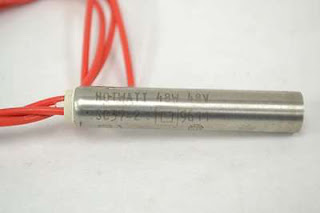
Cartridge heaters originally consisted of a ceramic-supported heating wire inserted into round metal tube, making them look like cartridges (the likely source of their name). They provide localized heat to restricted working areas requiring close thermal control. Their power density is less than 60 W/in2 and they generate temperatures up to 1,200°F. They range in diameter from 1/8 to 2 in. and vary in length from less than an inch to over four feet. Although they are usually round, they can have square or rectangular cross sections. Standard cartridge heaters account for an estimated 20% of all electric heaters made.
Compacted cartridge heaters were developed about 60 years ago and feature inorganic powder tightly compacted onto the heater wire. This increases their power density to nearly 500 W/in2 and maximum temperatures approach 1,800°F. The need for higher quality tubing and precision-fired crushable ceramics makes compacted heaters cost 1.5 to 3 times the cost of a standard cartridge. They are available in diameters from 1/8 to 1 in. and lengths from 1 inch to over 3 feet.
HOW ARE CARTRIDGE HEATERS MADE?
 |
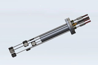
| Cartridge Heater Internal View |
HOW CAN YOU GET THE MOST EFFICIENT HEAT TRANSFER AND LONGEST OPERATIONAL LIFE OUT OF A CARTRIDGE HEATER?
There are several steps users can take. On installation, for example, cartridge heaters should be installed in holes drilled and reamed to no more than 0.002 inches larger than needed. The heaters are routinely sized to never be 0.005 less than the nominal diameter and always at least .001 under the nominal diameter for a slide fit. These close fits ensure rapid heat transfer from the heater to the housing and helps keep the heater as cool as possible, which contributes to a long life. Heaters should not be cycled from low to high temperatures as it shortens their life considerably. Instead, designers should calculate the proper wattage for their applications. The best wattage results in a 50/50 off/on cycle. For temperatures over 750°F, off/on control can be replaced by input voltage regulation through variable transformers or proportioning controllers to minimize temperature fluctuations. If a heater is going to be turned off routinely, the air around it should be kept dry and no impurities (oil, gas,) should be in contact with the heater. That’s because the ceramic material used in cartridge heaters is hygroscopic. Every time power to the heater is switched off, it creates a vacuum inside the cooling housing which draws in air and any nearby impurities from the surrounding area. The moisture or impurities, once inside the housing, can cause a short circuit and result in heater failure.
If a thermostat is used to control the temperature, it should be no more than 0.5-in. from the heater. Mounting it any farther away could let the unit run hot and thereby shorten its life. Another cause of failures is too high a watt density. If the heater was incorrectly specified for an application and provides too much heat, the heater will not be able to dissipate the heat and will fail. Similarly, if the heater is designed for 120 V but is being powered by 240 V, the output wattage will be four times greater than it should be, which can, again, lead to failure.
WHAT OPTIONS ARE AVAILABLE ON CARTRIDGE HEATERS?
There are several options and variations available. Heaters may be three-phase or multiple wattage in a single unit. For instance, an application might need quick heat ups and then a standby circuit to maintain a relatively low temperature using different wattages based on changing thermal loads. Heaters can have wattage outputs that vary over their lengths in order to even out temperatures over a platen or a large surface. Heaters can also have built-in thermocouples, usually at the bottom of the heater and type J or K grounded or ungrounded. If a precision fit is needed, companies can supply centerless ground diameters. They can also supply certain heaters at higher voltages (300 to 600 V).
Heaters used in corrosive environments can be Teflon coated or electro-polished. Heaters that need hermetic sealing or will be used in a vacuum application can be ordered with ceramic-to-metal seals that withstand temperatures to 1,000°F.
CAN CARTRIDGE HEATERS BE USED IN LIQUIDS AS IMMERSION HEATERS?
Yes, when applied with a mount- ing fitting. Not all cartridge heaters made as immersion heaters are completely moisture sealed. The heater and bushing are submersible but the termination end is not necessarily sealed. If an application is in a high humidity area, however, the termination area should be sealed. Seals can be silicone rubber or Teflon which are good to 400°F, or epoxy potting which can handle temperatures to 265°F.
WHAT ARE SOME OF THE TERMINATION OPTIONS OFFERED ON CARTRIDGE HEATERS?
There are multiple options for cartridge heaters, almost too many to list. Standard options start with straight internally connected leads. External connections are optional on larger sizes, recommended when repairable leads are required. There are also post terminals available on cartridges 15⁄16-in. and larger. For applications with limited space, manufacturers can supply right-angle leads.
There are also several options for protecting leads. Fiberglass or silicone rubber sleeving, as well as ceramic bead insulation, protect against temperatures up to 1,000°F. Additional protection can be provided using flexible conduit or stainless steel braid.
Have a requirement for cartridge heaters? Call BCE now at 510-274-1990 or visit https://belilove.com
