On-Off Temperature Control Using PLC Ladder Logic

on off control
Diagram of on / off control.
In control theory, an on–off controller is a feedback controller that switches abruptly between two states. It is often used as a control method for a process which can tolerate an ongoing, changing band of change, referred to as the hysteresis. A very common example for temperature are residential thermostats. They control the temperature of your home, turning off at your comfort setting, then after some significant change occurs, and they turn on again to eliminate that difference. The process cycles continually.

A common method of temperature control is an on/off control system using comparison instructions in a PLC program where outputs are energized until the set point is reached.

The video below provides a temperature control example where the heater turns on when the temperature falls to or below 597 degrees, and turns off when the temperature reaches 603 degrees or more.

To control the circuit, S1 is programmed in the heater output circuit. Addressed to the move instruction is a thermocouple that provides an analog value to the temperature. The temperature is moved from the source to the destination when S1 is activated and is displayed on the LED panel.

Using the less than or equal to, and greater than or equal to, instructions addressed to the same integer file the source values have A and B are compared to control the heater. With source a less than source be at the less than equal to instruction, the low temp and heater outputs are enabled. The heater remains on as long as the low temp output is true and the high temp output is false.

As the temperature rises above source B at the less than or equal to instruction, low temp turns off and heating continues. Reaching 603 degrees or more, the high temp output is enabled, since source A is equal to source B of the greater than equal to instruction.

When the high temp output is true, the heater turns off and remains of until the temperature reaches 597 or lower.  The cycle is repeated to maintain the average set point temperature at the other at 600 Fahrenheit.


Experience is Key When Applying Custom Electric Heating Elements

Electric Heater Design Expert
Heater design expertise is
readily available from your
Technical Sales Rep
Designing and applying custom electric heating elements are best completed and accomplished through the proper application of the right resources. One of the most available and important sources of high level technical knowledge is a vendor's local Technical Sales Rep. Their assistance is readily available and their consultative value is very high.  Bringing in a Technical Sales Rep will have a big bearing on a successful task or project completion.

Many Technical Sales Reps are degreed engineers. If they don't have an engineering degree, you'll find they have years of empirical application knowledge from working on many, many projects. You'll also find that many have worked at manufacturer's factories and know the in's and out's of production as well as anyone.

Consider these elements the Technical Sales Rep brings to your thermal system design project:

Custom heating element
Watt densities? Thermal profiles?
Distributed wattage?
There's a lot to know.
Product and Application Knowledge: Your Technical Sales Rep has probably seen hundreds, if not thousands, of custom heating requirements. They deliver a mental encyclopedia of product offerings, application insights, and broad spectrum of capabilities. They also have information regarding what products are in development that can give you the competitive edge. Much of this information resides in the Reps head, and is not generally accessible to the public via the Internet.

Experience: As a project engineer, the selection and incorporation of a new heater design may be all new to you. You may be treading on fresh ground with little or no experience in the nuance of electric heaters. There can be real benefit in connecting to a knowledgeable source, with years of past design and application experience, that will save you time, money, and effort.

Access: Technical Sales Reps work closely with a variety of manufacturers, and may even have in-house prototyping or manufacturing capabilities at their own companies. This gives you, the design engineer, a connection to “behind the scenes” manufacturer contacts with essential information not publicly available. The technical sales rep knows people, and makes it his/her business to know the people that can provide answers to your electric heating and custom thermal system application questions.

So, in this age of doing your own research and self-educating on the Internet, let's not forget the importance of a face-to-face visit with someone who can really help - your Technical Sales Rep. You'll be very pleased with the information they can provide to make your job easier and the quality of your product better.

Have a custom heater job? Contact BCE now!
www.belilove.com(510) 274-1990

Heat Transfer 101 for Industrial and OEM Applications

heat transfer
Heat transfer
shown by
melting ice.
When you need to apply heat in industrial applications, or for OEM part heating, everyone works under the same Laws of Thermodynamics. Whether your using electric heating elements or heating by steam, its imperative to understand the basics of heat and heat transfer.

Heat transfer is the movement of heat from one body or substance to another by radiation, conduction, convection or a combination of these processes. When heating a pan of water over a gas flame for example, all three forms of heat transfer are taking place. Heat from the flame radiates in all directions. Conduction takes place with the transfer of heat from the burner to the metal pan. This heat transfer is also responsible for making the handle hot after a period of time. The water is heated by the process up convection which is a circular movement caused by heated water rising and cold water falling.

The process of heat transfer also occurs when an object cools. If a mug of hot coffee is left standing on a cold kitchen countertop its temperature will gradually decrease as heat is lost. The heat energy dissipates by conduction through the mug to the table top, by convection as the liquid rises cools, and sinks, and by the radiation of heat into the surrounding air.

One way to conserve the heat of a liquid and prevent heat transfer is to place it in a thermos. The use use of a vacuum chamber with silvered surfaces along with low conductive materials can greatly improve the amount of heat or cold that is lost to the surrounding environment.

In between the silver glass walls of a thermos lies a vacuum. In the case of a hot liquid, heat transfer by convection through the vacuum is greatly restricted due to the absence have air molecules necessary to facilitate the transfer of heat. The lack of physical contact between the inside and outside walls of the thermos due to this airless space also greatly inhibits the movement of heat by conduction.

Heat loss by radiation is prevented by the silvered walls reflecting radiant energy back into the thermos. Some conduction of heat through the stopper and glass can be expected, but this too is limited because they are made of materials with very low conductivity. Thus the temperatures of both hot and cold liquids can be maintained by a properly designed thermos that limits the transfer energy through radiation, convection, and conduction.

Heat capacity is the amount of heat required to change the temperature of an object or substance by one degree Celsius. The heat capacity of water varies depending on its phase. As solid ice, the heat capacity of water is .5 calories per gram for every one degree Celsius, which means it takes half a calorie to raise the temperature of one gram of ice one degree Celsius. As a liquid, waters heat capacity is one calorie per gram for every one degree Celsius. So it takes one calorie of heat energy to raise one gram of water one degree Celsius.

The processes a phase change between solid liquid and gas also require a specific amount of heat energy. The amount of energy required to change a liquid into a solid or a solid into a liquid is known as heat of fusion. The amount of heat required to change one gram of ice to water is 80 calories. Similarly, the heat of vaporization is the energy required to transform a liquid into a gas. It requires 540 calories to change one gram of liquid water into a gas. With these values its easy to calculate exactly how many calories of heat energy are required to transform one gram of ice, at absolute zero, to steam.

To warm 1 gram a ice from -273 degrees Celsius, to 0 degrees celsius, would be 273 times .5 gram per calorie, or about 140 calories. The phase change of one gram a ice to liquid water requires 80 calories. Then to heat the water from zero degrees Celsius to 100 degrees Celsius with the heat capacity at one calorie per gram, would require 100 calories. The final phase change of one gram of boiling water to steam would require an additional 540 calories. Adding all of these values together yields 860 calories, the amount of heat energy it takes to transform one gram of ice, at absolute zero, to steam.

Epoxy Vacuum Feedthroughs for Medical Equipment, Analyzers, and R&D Laboratories

epoxy feedthrough
The challenges of getting data and
control sensors inside
vacuum equipment.
Scientists and researchers are continually challenged to come up with better ways to read data inside a vacuum environment. Traditional ceramic and glass-to-metal vacuum feedthroughs don’t offer the flexibility of design required. Unique varieties of control and data signals have to pass through the wall. Not only are electrical power and control signals being passed, but fiber optic cables and pneumatic tubing may be included. Ever changing variables, such as the number and types of connectors, unique geometries, and limited available space, make it very difficult to find an off-the-shelf feedthrough. As a result, designers have traditionally been forced to make compromises and specify a feedthrough with some, but not all, of the desired specifications.

custom epoxy feedthrough
Custom epoxy feedthrough by BCE
This reality has led to significant gains in custom epoxy feedthrough development. Epoxy feedthroughs overcome design restrictions. New epoxy properties have been developed that rival ceramic and glass in performance. High performance, clear epoxy potting opens the door for researchers to specify the exact number and type of wires, fiber optic cables, or any other insert they require.

Manufacturers of epoxy feedthroughs can provide a virtually limitless variety of wires, cables, or tubes along with the added benefit of fast prototyping and small production runs - perfect for the research and manufacturing community.

Epoxy vacuum feedthroughs are quickly becoming the preferred vacuum entry device because:
  • Can accommodate custom conductors, angles, and shapes.
  • Prototypes with the exact number and type of have fiber-optic cables, pneumatic tubing, or run wires.
  • Electrical shielding is not a problem.
  • Epoxy feedthroughs are cost-effective.
  • Comply with outgassing specifications.
  • Allow for visual inspection when clear epoxy used.
  • Feedthroughs can be mounted directly to flexible circuits and printed circuit boards.
  • Elimination of contact resistance.
With the development of epoxy feedthroughs medical device companies, analyzer manufacturers, laboratories, aerospace companies, and other R&D facilities can design their equipment based on optimal size, cost and performance, and not be forced to compromise by ceramic and glass-to-metal feedthroughs limitations.

Because of the constant pressure on vacuum equipment researchers and OEM designers for “better, faster, smaller”, it’s clear that epoxy feedthroughs provide flexibility and options which allow for more efficient and creative design.

For more information regarding epoxy vacuum feedthroughs, contact:
BCE
www.belilove.com
(510) 274-1990

Epoxy Vacuum Feedthroughs for Electrical and Fiber Optic Applications

epoxy vacuum feedthroughs
Epoxy vacuum feedthroughs
provide faster prototyping and
meet customer needs.
More and more OEMs and research facilities are turning to epoxy feedthroughs for their vacuum chamber challenges. New epoxies are available that rival glass and ceramic feedthroughs in performance. Faster prototyping, and lower short-run costs are making epoxy feedthroughs very attractive.

Ceramic and glass-to-metal feedthroughs typically are not available in the exact form required by scientific researchers and equipment manufacturers. There is a tendency to settle or accept off-the-shelf feedthroughs as a compromise, thinking that custom ceramic or glass feedthroughs in small quantities would break the bank, not to mention take forever to deliver. Not true.

epoxy feedthrough
Epoxy feedthrough
Today’s epoxy vacuum feedthroughs make prototyping and manufacturing easier, with higher production output and lower overall costs. Here are some of the features that make this true:
  • Custom conductors, angles, and shapes are not a problem
  • Prototype designs can be provided with fiber-optic cables, pneumatic tubing, and wires (with or without shielding)
  • Compared to ceramic or glass, custom epoxy feedthroughs are cost-effective
  • Feedthroughs comply with NASA outgassing specs
  • Visual inspection is possible because of the clear epoxy used
  • The feedthroughs can be mounted directly to flex-circuits and printed circuit boards
  • Tighter specification can be achieved because contact resistance and voltage drop is eliminated

Epoxy vacuum feedthroughs come custom built to your unique specifications and ensure your equipment performs to the level you specify, so it's important to work with an experienced, capable manufacturer of epoxy feedthroughs. In today’s ultra-competitive marketplace, working with the right partner can mean the difference between success and failure. Manufacturer’s are constantly looking smaller, more compact parts, with faster deliveries and lower costs. Pick a vendor for your vacuum feedthroughs that understands this and has the in-house technology and processes to keep you ahead of the curve.

For more information on epoxy vacuum feedthroughs, contact:
BCE
(510) 274-1990

Ceramic Thick-Film Heaters for OEM Analytical and Medical Equipment

ceramic heating element
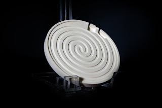
Ceramic heating element
Manufacturers of laboratory and process analytical equipment, as well as medical equipment, are continually challenged to make products smaller and more compact. Smaller, more efficient components are always in demand. Providing heat for sample stability or a chemical reaction is a common requirement. There's an ongoing challenge to find smaller and more efficient electric heaters.

Many traditional electrical heating elements are limited in size and efficiency due to the balance required between conductor temperatures and the the heat transfer properties of the dielectric material used in their construction. Sometimes the mass required to insulate electrically is at odds with the ability to drive the heat into the part.  Metal sheathed heaters use compacted magnesium oxide, or wafers of mica for dielectric. While these provide good electrical insulation, they also inhibit thermal transfer from resistance element to the external part. Flexible heating elements use a variety of rubbers or fluoropolymer elastomers that sandwich the resistance element. While these designs are dielectrically strong, and allow for excellent heat transfer, they are limited by the maximum operating temperatures and watt densities of the elastomer.

A newer, alternative technology is “thick-film” ceramic heaters, a process of depositing a resistor “trace” of tungsten paste on top of a ceramic part in a process very similar to screen printing. The deposition process allows for close control of thickness and width of the resistor, thus accurately controlling the conductor resistance, wattage, watt density, and uniformity of the heated part.

The use of ceramics as the heater body (referred to as a heated part), has many advantages. Ceramics are chemical inert, offer excellent thermal conductivity, impervious to moisture, and are very durable. The downside to using ceramics as heaters, however, is the difficulty in machining to very tight tolerances. In recent years though, many of the ceramic machining hurdles have been overcome through advanced ceramic machining processes.

In the early years of development thick-film ceramic heaters had a few major challenges. Dealing with mis-matched expansion coefficients between the ceramic substrate and the conductor trace was considerable. Years of research now have yielded excellent data on compatible materials making this problem much less significant. Another challenge is controlling the tolerance and repeatability of the heater resistance from part-to-part. Improvements and advancement in this area are made possible with laser etching, tighter screening procedures, and advanced machining.

The use of ceramics provided many interesting possibilities in heater design, and many materials were tested and researched. The most common ceramics used for thick-film heaters today are alumina (Al2O3), silicon nitride (Si3N4), beryllium oxide (BeO), and aluminum nitride (AlN). Each material has its own unique chemical and physical properties, but all exhibit good thermal conductivity and good dielectric properties.

The combination of excellent thermal conductivity, high dielectric, high watt densities, precise thermal profiling, and custom shapes and sizes that make thick-film ceramic heaters so attractive to equipment manufacturers. Providing more heat in smaller areas is easier than with traditional heaters. Additionally, some of the ceramics used are non-contaminating and moisture-proof, making them excellent candidates for clean and ultra-clean applications.

Ceramic thick-film heaters have many advantages over metal or elastomer sheathed heaters beyond just providing a more compact component. They are very fast acting, durable, moisture proof,  and contamination proof. They can be designed and machined to virtually any size or shape, watt density, voltage, and distributed wattage profile. While the initial design and prototyping requires investment in time and money, the resulting product can be mass produced economically and with repeatable accuracy and quality.

For more information, contact:
BCE
(510) 274-1990
www.belilove.com