Epoxy Vacuum Feedthroughs for Electrical and Fiber Optic Applications

epoxy vacuum feedthroughs
Epoxy vacuum feedthroughs
provide faster prototyping and
meet customer needs.
More and more OEMs and research facilities are turning to epoxy feedthroughs for their vacuum chamber challenges. New epoxies are available that rival glass and ceramic feedthroughs in performance. Faster prototyping, and lower short-run costs are making epoxy feedthroughs very attractive.

Ceramic and glass-to-metal feedthroughs typically are not available in the exact form required by scientific researchers and equipment manufacturers. There is a tendency to settle or accept off-the-shelf feedthroughs as a compromise, thinking that custom ceramic or glass feedthroughs in small quantities would break the bank, not to mention take forever to deliver. Not true.

epoxy feedthrough
Epoxy feedthrough
Today’s epoxy vacuum feedthroughs make prototyping and manufacturing easier, with higher production output and lower overall costs. Here are some of the features that make this true:
  • Custom conductors, angles, and shapes are not a problem
  • Prototype designs can be provided with fiber-optic cables, pneumatic tubing, and wires (with or without shielding)
  • Compared to ceramic or glass, custom epoxy feedthroughs are cost-effective
  • Feedthroughs comply with NASA outgassing specs
  • Visual inspection is possible because of the clear epoxy used
  • The feedthroughs can be mounted directly to flex-circuits and printed circuit boards
  • Tighter specification can be achieved because contact resistance and voltage drop is eliminated

Epoxy vacuum feedthroughs come custom built to your unique specifications and ensure your equipment performs to the level you specify, so it's important to work with an experienced, capable manufacturer of epoxy feedthroughs. In today’s ultra-competitive marketplace, working with the right partner can mean the difference between success and failure. Manufacturer’s are constantly looking smaller, more compact parts, with faster deliveries and lower costs. Pick a vendor for your vacuum feedthroughs that understands this and has the in-house technology and processes to keep you ahead of the curve.

For more information on epoxy vacuum feedthroughs, contact:
BCE
(510) 274-1990

Ceramic Thick-Film Heaters for OEM Analytical and Medical Equipment

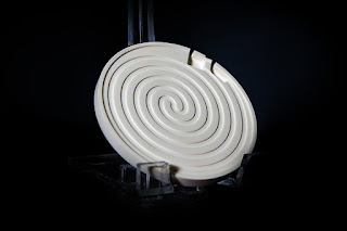
ceramic heating element
Ceramic heating element
Manufacturers of laboratory and process analytical equipment, as well as medical equipment, are continually challenged to make products smaller and more compact. Smaller, more efficient components are always in demand. Providing heat for sample stability or a chemical reaction is a common requirement. There's an ongoing challenge to find smaller and more efficient electric heaters.

Many traditional electrical heating elements are limited in size and efficiency due to the balance required between conductor temperatures and the the heat transfer properties of the dielectric material used in their construction. Sometimes the mass required to insulate electrically is at odds with the ability to drive the heat into the part.  Metal sheathed heaters use compacted magnesium oxide, or wafers of mica for dielectric. While these provide good electrical insulation, they also inhibit thermal transfer from resistance element to the external part. Flexible heating elements use a variety of rubbers or fluoropolymer elastomers that sandwich the resistance element. While these designs are dielectrically strong, and allow for excellent heat transfer, they are limited by the maximum operating temperatures and watt densities of the elastomer.

A newer, alternative technology is “thick-film” ceramic heaters, a process of depositing a resistor “trace” of tungsten paste on top of a ceramic part in a process very similar to screen printing. The deposition process allows for close control of thickness and width of the resistor, thus accurately controlling the conductor resistance, wattage, watt density, and uniformity of the heated part.

The use of ceramics as the heater body (referred to as a heated part), has many advantages. Ceramics are chemical inert, offer excellent thermal conductivity, impervious to moisture, and are very durable. The downside to using ceramics as heaters, however, is the difficulty in machining to very tight tolerances. In recent years though, many of the ceramic machining hurdles have been overcome through advanced ceramic machining processes.

In the early years of development thick-film ceramic heaters had a few major challenges. Dealing with mis-matched expansion coefficients between the ceramic substrate and the conductor trace was considerable. Years of research now have yielded excellent data on compatible materials making this problem much less significant. Another challenge is controlling the tolerance and repeatability of the heater resistance from part-to-part. Improvements and advancement in this area are made possible with laser etching, tighter screening procedures, and advanced machining.

The use of ceramics provided many interesting possibilities in heater design, and many materials were tested and researched. The most common ceramics used for thick-film heaters today are alumina (Al2O3), silicon nitride (Si3N4), beryllium oxide (BeO), and aluminum nitride (AlN). Each material has its own unique chemical and physical properties, but all exhibit good thermal conductivity and good dielectric properties.

The combination of excellent thermal conductivity, high dielectric, high watt densities, precise thermal profiling, and custom shapes and sizes that make thick-film ceramic heaters so attractive to equipment manufacturers. Providing more heat in smaller areas is easier than with traditional heaters. Additionally, some of the ceramics used are non-contaminating and moisture-proof, making them excellent candidates for clean and ultra-clean applications.

Ceramic thick-film heaters have many advantages over metal or elastomer sheathed heaters beyond just providing a more compact component. They are very fast acting, durable, moisture proof,  and contamination proof. They can be designed and machined to virtually any size or shape, watt density, voltage, and distributed wattage profile. While the initial design and prototyping requires investment in time and money, the resulting product can be mass produced economically and with repeatable accuracy and quality.

For more information, contact:
BCE
(510) 274-1990
www.belilove.com

Suggested Watt Densities for Electric Heating Elements

watt density in electric heaters
Always consider proper watt density
for your electric heater application.
Reprinted with permission from Hotwatt

The rates below are recommended watt densities for use with various materials. Safe values vary with operating temperature, flow velocity, and heat transfer rates. In general, the higher the material temperature, the lower the watt density should be, especially those materials which coke or carbonize, such as oils. Watt densities should be low if a material is being heated to a temperature near where the change of state to a vapor occurs (water to steam @ 212°F) since the vapor state has much poorer heat transfer capabilities.

Material being heated Maximum Operating Temp.°F Maximum Watts Per Sq. In.*
Acid Solutions:
   Acetic
   Chromic (5%)
   Citric
Ferric
   Chloride (40%)
Hydrochloric
Nitric (50%)
Sulphuric

212
Boiling
Boiling
Boiling

150
Boiling
Boiling

40
40
40
40

30
40
30
Alkali & selected oakite cleaning solution 212 40
Asphalt binder, tar, other viscous compounds 200
300
400
500
8
7
6
5
Caustic Soda 2%
                    10%
                    75%
210
210
180
45
25
25
Coffee (Direct Immersion) Boiling 90
Dowtherm A®
   flowing at
   1 ft/sec or more
   Non-flowing


750
750


22
10
Ethylene glycol 300 30
±Fuel Oils
   Grades 1 & 2 (Distillate)
   Grades 4 & 5 (Residual)
   Grade 6 & Bunker C
   (Residual)
200
200
160
22
13
8
Gasoline, kerosene 300 20
Glue (heating indirectly using water bath Lead-Stereotype pot) 600 35
on
casting
Liquid ammonia plating baths 50 25
** Lubrication Oils
   SAE 10, @ 130°F
   SAE 20, @ 130°F
   SAE 30, @ 130°F
   SAE 40, @ 210°F
   SAE 50, @ 210°F

250
250
250
250
250

22
22
22
13
13

* * Some oils contain additives that will boil or carbonize at low watt densities. Where oils of this type are encountered, a watt density test should be made to determine a satisfactory watt density.


Material being heated Maximum Operating Temp.°F Maximum Watts Per Sq. In.*
Metal melting pot 500 to 900 20-27
Mineral oil 200
400
20
16
Molasses 100 2-3
Molten salt bath 800-950 40
Molten tin 600 20
Oil draw bath 600
400
20
24
Paraffin or wax 150 16
Photographic solutions 150 70
Plating solutions:
   Cadmium plating
   Chrome plating
   Copper plating
   Nickel plating
   Tin plating
   Zinc plating

40
40
40
40
40
40
Salt Bath 900 30
Sea Water Boiling 90
Sodium cyanide 140 40
Steel tubing cast into aluminum 500 to 750 50
Steel tubing cast into iron 750 to 1000 55
Heat transfer oils
   flowing at 1 ft/sec or more
500
600
650
750
22
22
22
15
Trichloretylene 150 20
Vapor degreasing solutions 275 20
Vegetable oil (fry kettle) 400 30
Water (process) 212 60
Water (washroom) 140 80-90

* Maximum watt densities are based on heated length, and may vary depending upon concentration of some solutions. Watt density should be kept as low as possible in corrosive applications since higher watt densities accelerate corrosive attack on element sheaths. Consult BCE for limitations.

Important: The above values are estimates. It is strongly suggested that you discuss your requirement with an application expert before you apply any electric heating element in to a process where the proper watt density is unknown.

Attending MD&M West and the Value of Exhibitions

medtech world
Visit BCE at booth 2184
This week BCE is exhibiting at MD&M West (Medical Design and Manufacturing West) in Anaheim, CA. While the title implies medical equipment design, the exhibition also includes packaging equipment and other related equipment. The show runs Feb. 9, 10 and 11.

MD&M is the world's largest medical design and manufacturing exhibition. It "offers three days of technical presentations, hands-on design workshops, demonstrations and ticks and tricks to help you stay ahead of the game in 2016."

Representatives from many well-know "Medtech" companies will attend and a full 3 days of presentations are planned. Some of the more interesting titles are "The Creative Keys: How to Turn a Thought Into a Thing with Ease and Grace", "New Product Development Technologies and NexGen Applications", and "Leading the Smart Manufacturing Revolution".

BCE's Applied Resistance Group will showcase its thermal system design capabilities, advanced ceramics machining, laser machining, and thick film circuits and heaters. BCE is quickly developing a nation-wide reputation as an excellent partner for these products.

BCE Applied Resistance
BCE is exhibiting their
years of experience in
thermal system design,
thick film, laser machining,
and advanced ceramics.
BCE has decades of hands-on experience with thermal systems and advanced ceramics. The result is a strong expertise in analytical instrumentation, semiconductor equipment, photovoltaic devices, medical equipment, plastics processing machinery, foodservice equipment, packaging machinery, aerospace technologies, and laboratory R&D.

Exhibitions and trade shows are great places to network and build business relationships. Face-to-face contact with prospective customers and vendors provide an opportunity for strong business relationship foundations. Meeting with someone in person is far better than meeting online.

One huge benefit of attending an exhibition is the ability to meet large numbers of helpful people in one place. When attending an exhibition, it's best to plan ahead and utilize your time efficiently. Set up appointments in advance so that you don't waste time wondering. Make a list of booths and people you really want to get to know. And please, stop by the BCE booth (2184) - you'll be glad you did.