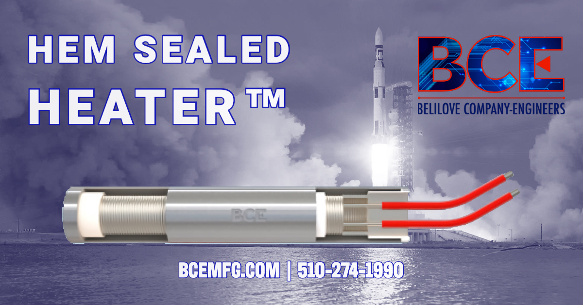
HEM Sealed Heater™ - Bench Test to 250°C

HEM Sealed Heater

In addition to optimizing liquid flow in space launches, more research and design facilities require a heater that will work in vacuum without outgassing the internal resistor and insulating materials.  Materials such as chromium and particles from the magnesium oxide begin to outgas.  Placing a vacuum barrier that keeps these particles in place and allows the operator to process without consistently replacing heaters, should increase productivity.

HEM Sealed Heater™/ Vacuum Chambers:
  • Temperature range of -55⁰C to +200⁰C Sheath Temperatures
  • Stainless steel 321 for heated zone, 304 Hem Sealed Cap   
  • 18AWG to 32AWG Kapton®/polyimide Lead wires 
  • 500Watt (± 10%) , 240 Volt, 1-phase   
  • He Leak Tested = 5 x 10¯⁹ ATM, CC/sec or better 
  • Hi-Pot Test 1K*2E 1 2 seconds (1500-2250VDC 0.5mA) 
  • Meg-Ohm 20 to 4,000+ @ 500VDC 

OUTCOME:

This test was performed in atmosphere within a 3.5 hour time frame.  The temperature was held each hour after the initial ramp to sheath temperature as noted in the graph below.

The temperature of 200°C was held for the 2nd hour and then the heater was powered ~250°C and held until the test was complete after about 3.5 hours.  

At lower temperatures of ~200°C, the Hem Sealed™ Cap reached 60°C keeping the vacuum integrity as per the maximum heater transition temp of 70°C.  The maximum temperature on the sheath tested was to 250°C with the Hem Sealed™ Cap at 79°C.

Special note; if a heater block or other device being heated, the optimal bore diameter vs heater diameter for the best heat transfer should be +.0020” to +.0025”.


BCE

+1 510-274-1990

The Role of Vacuum Feedthroughs

The Role of Vacuum Feedthroughs in High Vacuum Applications

Vacuum feedthroughs are devices that are used to allow electrical, optical, or fluid connections to pass through a vacuum chamber wall. They are essential in high vacuum applications because they allow for the passage of electrical power, control signals, and other types of data into and out of the vacuum chamber while maintaining the integrity of the vacuum.

There are several reasons why vacuum feedthroughs are important in high vacuum applications. First and foremost, they allow for the passage of electrical power and control signals into the vacuum chamber, which is necessary for operating many types of equipment and instruments that are used in high vacuum environments. For example, electrical feedthroughs can be used to power a vacuum pump, while optical feedthroughs can be used to transmit data from sensors or cameras that are located inside the vacuum chamber.

In addition to electrical and optical connections, vacuum feedthroughs can also be used to transport fluids, such as coolants or process gases, into or out of the vacuum chamber. This is particularly important for applications that require temperature control or precise gas delivery, such as in the case of thin film deposition or material processing.

Another important aspect of vacuum feedthroughs is that they can be designed to minimize the amount of outgassing that occurs, which is the release of gas from the feedthrough material into the vacuum chamber. This is important because outgassing can contaminate the vacuum environment, potentially causing damage to the equipment or samples inside the chamber.

Lastly, vacuum feedthroughs must be designed to withstand the high vacuum conditions and operate efficiently and reliably. These feedthroughs typically consist of a metal or ceramic stem with an epoxy, glass or ceramic seal that allows the electrical, optical, or fluid connection to pass through the vacuum chamber wall. The feedthrough stem must be sealed to the vacuum chamber wall without leaking, while the electrical, optical, or fluid connections must maintain their integrity under the high vacuum conditions.

In summary, vacuum feedthroughs play a crucial role in high vacuum applications, by allowing electrical, optical, or fluid connections to pass through the vacuum chamber wall while preserving the high vacuum condition. They also play a important role in controlling temperature, providing gases and maintain the integrity of the electrical, optical and fluid connections.

BCE

+1 510-274-1990

Happy Holidays from BCE!

Happy Holidays

Semiconductor Processing Chuck Heaters

Semiconductor Processing Chuck Heaters

In semiconductor processing, electric chuck heaters are used to heat the surface of a chuck, which is a device that holds a wafer in place during processing. The chuck is typically made of aluminum or copper and is used to hold the wafer during the various processing steps, such as photolithography, etching, and deposition. The chuck is typically cooled to prevent thermal damage to the wafer during processing, but it must also be heated to maintain a consistent temperature and prevent thermal gradients across the wafer.

The electric chuck heater consists of a heating element, typically made of resistive wire, that is embedded in the chuck. When current is passed through the heating element, it generates heat, which is conducted through the chuck and heats the surface of the chuck. The temperature of the chuck is controlled by adjusting the current flowing through the heating element.

The use of electric chuck heaters in semiconductor processing is important for several reasons. First, it helps to maintain a consistent temperature across the wafer, which is important for maintaining process repeatability and yield. Second, it helps to prevent thermal gradients across the wafer, which can cause warping and other defects. Finally, it can help to prevent contamination of the wafer by preventing condensation on the chuck surface.

BCE

+1 510-274-1990

Happy Thanksgiving from BCE

Happy Thanksgiving from BCE

Mini Clean Flow (MCF) Air Heater – Three Phase

Mini Clean Flow (MCF) – Three Phase

BACKGROUND 

The application requirement was a 2” Stainless Steel heater capable of 120 CFM with a 250⁰C outlet temperature.  The inlet temperature was ambient air.  The heater required two Conflat Flanges (CF2.75), which could be used in a parallel flow configuration at the customer site.  The heater needed to be air tight.    

SCOPE

MCF – Three Phase:
  • 250⁰C @ 120CFM using (2) units in a parallel flow pattern
  • Stainless steel 304, all wetted parts 
  • Pressure tested to 90 PSI (or equivalent 5 x 10 ¯⁴ ATM, cc/sec or better)  
  • 3-phase with three heated zones 
  • (3) independent internal type “K” thermocouples for each zone 
  • 11KW (± 10%) , 240 Volt, 3-phase (or 1-phase optional) 
  • 36” Lead wires for each zone with 12” wire braid for strain relief
  • 304SS CF 2.75 inlet and outlet flange   
  • Medium being heated: Air, ambient  
  • He Leak Tested = 5 x 10¯⁴ ATM, CC/sec or better 

OUTCOME

The heater was laser welded on the flanges and brazed on the heater zones.  The heater helium leak test passed up to 1 x 10 ¯⁸ cc/sec in during the testing phase.  There were no problems heating ambient air at 2.5CFM to 200°C during the live power test at BCE.  The part was cleaned and passed the required 700 Volt DC Hi-pot test for 5 seconds @ 0.5mA.  

Mini Clean Flow (MCF) – Large DI Water Heater

Mini Clean Flow (MCF) – Large DI Water Heater


BACKGROUND:

Deionized water application requiring the recirculation of 3 gallons per minute to reach 66ºC in 2 hours. NEMA 4 moisture resistant housing was required.

SCOPE:

MCF – Large DI Water Heater:
  • Temperature from 18ºC to 66ºC in 2 hours
  • 316 Stainless Steel All wetted parts
  • Pressure tested to 90 PSI
  • NEMA 4 Housing
  • RTD, 3-wire 100 ohm process sensor built-in near outlet
  • An additional TC for bottom temperature read
  • 16KW (± 10%) , 208 Volt, 3-phase
  • Mounting threads on the bottom of the assembly
  • Medium being heated: Deionized Water (DI Water)
  • Recirculate at 3gpm

OUTCOME:

The heater zones were individually heated at lower voltage then pressure tested up to 90 PSI at 20ºC - 25ºC. The typical ramp temperature for a bench test prior to shipping is 100ºC. The response time in an air medium environment was immediate as the temperature was achieved in under 20 minutes. All zones passed the recommended 700 VDC for 5 seconds on the Hi-Pot test prior to shipping. The heater was cleaned & packaged then sent out for delivery.

BCE

+1 510-274-1990